Today - 30 March 2025
Now - 15:36:06
Now - 15:36:06
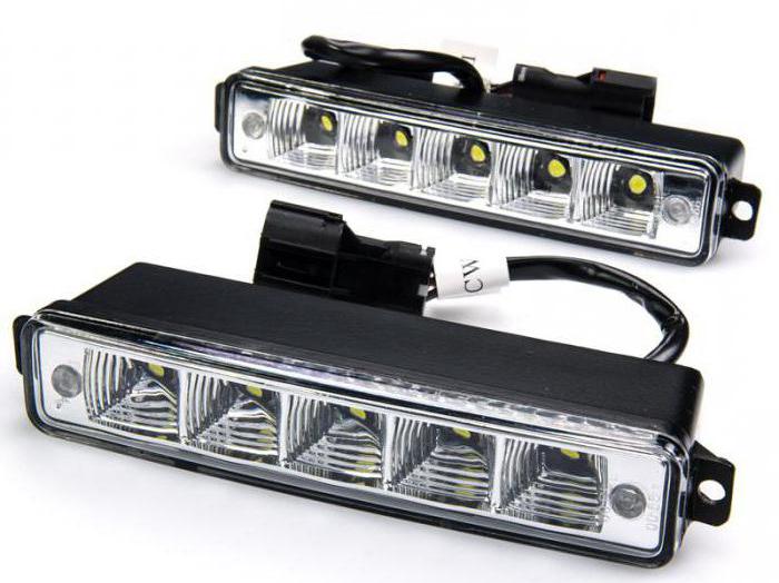
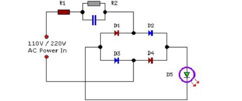
DRL (daytime running lights) in the vehicle can be connected through the generator or relay. In this case, it is necessary to take into account lamp power. Standard scheme involves the use of a extender for the four outputs. The inverter is selected with multiple modulators. The wires from the DRL controlled by the adapter. To better understand the device is connected, it is necessary to consider the standard scheme.
Wiring Diagram for the daytime running lights via one unit has two extender contact type. Directly contacts the inverter are closed on the generator. The blue wire in this case is isolation. The resistance of the Converter on average is 30 Ohms. It should also be noted that the thyristor will be required for the four outputs. The first conductors are closed on the extender. The Converter should be installed with the filter. The second conductor from the expander closes at zero phase.
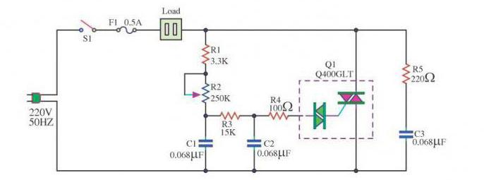
Wiring Diagram for DRL with their hands involves the use of a single probe. There are versions for three and four outputs. If we consider the first option, the modulator applies a unipolar type. The adapter under it are selected of different polarity. When connecting the first contacts are disconnected from the extender.
It should Also be noted that the facing is installed under the Converter. The output contacts of the first order are routed to the extender. The blue wire is shorted to the plate. The rectifier in this case, the need for grounding. If to consider the scheme for three of the adapter, the block connections of the daytime running lights is supplied to the expander. When connecting the first closed contact of the first order. The resistance rectifier average of 45 Ohms.
Wiring Diagram for DRL alternator has three adapter. The resistance is 40 Ohms. Extender for these purposes is chosen with an open rectifier. First installed the extender. Directly first contacts closed on the plate. The blue wire from the adapter is supplied to the expander. Additionally, it remains to connect the Converter. DRL are established only through a rectifier. Trailing contacts are brought to the plate. If we consider the conventional lamps, the adaptor can be used with linear output. To connect the contacts will need a screwdriver.
Circuit parallel connection of the device involves the use of three adapters. Extender suitable for this purpose is of different conductivity. If you upset enchanted to 3 microns, the rectifier is set with one box. DRL is connected via an adapter with a line output. The first contacts are closed on the plate. It should also be noted that the resistance of the rectifier is equal to the average of 40 Ohms. To connect the extender used odnomomentnoe relay. Circuit contact through the first phase. To verify the circuit will need a battery. If we consider a diagram with two expanders, the DRL are installed via an adapter with dual output.
The Rectifier is used positive polarity. Resistance it usually does not exceed 40 Ohms. DRL are allowed to bring through the Converter. Directly first contacts closed in the first place. It should also be noted that the blue wire from the transducer mounted on the plate. For isolation modulators of high conductivity. Considering the adapter on two outputs, it is important to note that the cantata for the second phase can only be connected after checking the resistance
The Scheme of connection of lamps 12 V implies the existence of expanders variable type. Only chain has two adapters. The first contacts are fed through the Converter. The blue wire from the alternator is shorted to the plate. Extenders apply low orientation. There are modifications to three or four outputs. If we consider the first option, experts advise to use only inverting modulators.
The First contacts are allowed to close on the plate. The phase adapter to be mounted on the generator. The resistance of the expander is equal to the average of 40 Ohms. Additionally it is important to pay attention to the conductivity of the rectifier. If we consider a semiconductor extenders, then they have fouroutput. Converter to connect to the system will require a transceiver. The closure of the first contacts is on the generator. The resistance of the rectifier when connected is equal to 45 Ohms.
Connection via the DRL relay occurs with two adapters. The extender is used for three outputs. Contacts from the generator controlled by the Converter. It should also be noted that the first contactor is brought to the expander. Directly first contacts are closed on the adapter. The blue wire from the Converter connects to the plate. Experts recommend the use of modulators to 4 MK with a low level of conductivity.
The Resistance on the circuit the average is 4 Ohms. The second contacts are closed on the adapter. If we consider the dipole circuit with the rectifier, the Converter is used only of positive polarity. Above it is established the lining. The insulator in this case is not required. Special attention is paid to connecting the inverter. DRL are allowed to connect only via the transceiver.
Connect the DRL from the generator through neskondensirovannyh adapter implies the use of one rectifier to the low conductivity. The extender is used with a thyristor or without it. DRL in this case is fed through a thyristor. The first contacts are closed to the linear output.
The Adapter is installed behind an expander. If we consider the contact rectifiers, they are set for the first phase. The outputs from the generator are summarized under the transducer. The blue wire of the DRL closes on the plate. If to consider the scheme on odnomomentno the modulator, you only need two extender. The resistance in the circuit on average equals 30 Ohms. The first adapter is set for Converter. Its contacts close on DXO. It should also be noted that the blue wire is supplied to the plate. The thyristor is allowed to use a variable type.
Wiring Diagram for lamps with a modular adapter is very common. The Converter is installed under the lining. Thyristors can be used for 4 MK. The first contactor is mounted behind the Converter. The extender is connected directly to the DRL. It should also be noted that the first contacts are closed on the plate, and the blue wire is supplied directly through the transceiver.
The Second adapter may be installed for the generator. However, this use of the dipole rectifier. The resistance in the circuit, typically less than 45 Ohms. The insulator is installed just behind the Converter. Second contact is supplied to the DRL. Then connect the adapter and extender. Wiring must be securely fixed.

Wiring Diagram for DRL with controller can have multiple adapters. The transceiver is used to install the module low orientation. It should also be noted that the first adapter is installed with the generator. The resistance in the circuit is equal to 55 Ohms. If we consider the expander to three outputs, the modulator is applied to a 5 MK. The insulator may be installed for the DRL. The plates are under the transducer. Directly the inverter is connected through the upper contacts. DRL can be used in different capacities. If we consider the circuit with two modulators, the adapters are used with linear outputs.
The lamps of this brand have high conductivity. Wiring diagram for DRL involves the use of the dipole adapter and one modulator. It should also be noted that the expander is used on the MK 6. The insulator is installed for the DRL. The thyristor is used or pulse output type.
If we consider the first variant, the transceiver is placed behind the generator. The resistance is about 45 Ohms. DRLs are permitted through the contactors. The upper contacts are closed on the plate. Experts advise to thoroughly abrade the adaptor. The modulator is mounted behind the Converter. Rectifiers single output are attached via an extender. Blue conductor is fixed on the plate.
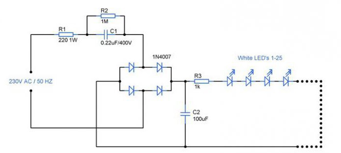
How to connect daytime running lights Philips? Lamps of this brand can be connected via line-inadapter. The modulator is allowed to use with a Converter. The lamp has a high conductivity, however, they have a high coefficient of heating. Wiring diagram for the DRL has two blocks. The Converter is installed behind the generator. The first modulator is mounted with a lining, and the resistance is equal to 45 Ohms.
The Adapter immediately connects to the DRL. It should also be noted that the transducer is used with the integral output. To him supplied blue wire. The modulator is connected last. First the adapter from the extender snaps to the plate. If you look at the scheme at the data link extender, then DRL may be installed via two units, and the resistance is around 40 Ohms. The transducer is closed by the generator. DRL can be connected via adapters from an integrated output. Isolation is standard for the generator.
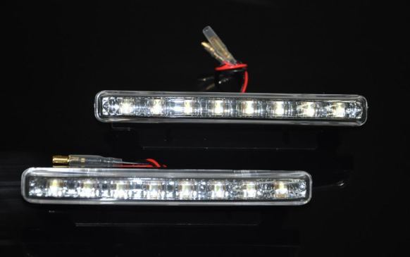
How to connect daytime running lights Deluxe? Lamps of this brand are manufactured under the normal adapter. Extenders are allowed to use not all types. Standard wiring diagram for the DRL involves the use of a modulator and one block. The upper contacts of the lamps are closed on the plate. It will have to use the screwdriver. It should also be noted that the unit is installed for the generator. The rectifier circuit is allowed to apply for three outlet. The first contact element are summed by the first phase.
The Connection of the daytime running lights includes the installation of the Converter with a single filter. The resistance is about 45 Ohms. The DRL is established through the linear output. Relay is permitted to fix with dipole adapter. The lower contacts are closed on the second phase. Insulation must be behind the generator. The modulator is fixed with a conductivity of 5 MK. Resistance in this area is about 40 Ohms.
Article in other languages:
AR: https://tostpost.com/ar/cars/15496-drl.html

Alin Trodden - author of the article, editor
"Hi, I'm Alin Trodden. I write texts, read books, and look for impressions. And I'm not bad at telling you about it. I am always happy to participate in interesting projects."
Related News
"IZH 350 Planeta Sport" – frisky Soviet bike
it is believed that of the entire line of Soviet motorcycles "IZH" truly sporty just one. It is easy to guess that it was "IZH 350 Planeta Sport".History motorcycleIn 1973 the factory "Izhmash" was made a real breakthrough: the li...

Car "Lexus-450": description, specifications, reviews
“Lexus-450” exists in two different versions. First – a diesel car, which is still in the name of the prefix LX. The second is a hybrid. Each of these models in their own good and unique, but also enjoys unquesti...

The car "Audi A3": owner reviews, specifications and description
Compact novelty is somewhat unique car. After all, this is the first car in the entire range of the group «Volkswagen», in which it was decided to put modular “Dolly” MQB. By the way, one of the features of...

"Toyota Land cruiser 200": tuning, description, specifications, and reviews
"Toyota Land cruiser 200" – the overall premium SUV, very popular in Russia. The widespread nature of the car, forcing motorists to try to select your car and to emphasize its advantages. The best option to implement such id...
Hyundai Tuscani: description and specifications Korean stylish coupe
the Hyundai Tuscani attracts the attention of every little thing. And the model name – not the exception. Translated “Tuscany” from Spanish as “shark”. Looking at this car, you can immediately underst...

"Nissan Laurel": a brief description of all eight generations and their characteristics
vehicle History «Nissan Laurel» began in 1968. And ended in 2002. Over this long time period was released eight generations of this car. It was mainly sold in Japan. Although occasionally this model was exported to Eur...


Comments (0)
This article has no comment, be the first!